Once all of the angled cuts have been made, and all sections have had
their cut edges lightly sanded to remove burrs, it is time to to assemble
the instrument.
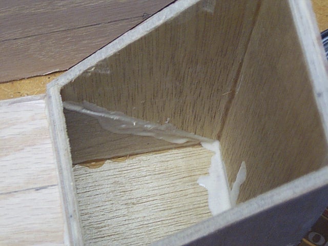
Start by laying the 'down tube' section down, with the large end opening
facing up. Lay the small 'bottom bow' section on top of this opening, as
shown in the photo. Make sure to place the smaller end of the bottom bow
section onto the down tube section. Check the two sides of the bore to
make sure the center lines are in alignment.
Once comfortable with the fit and the way it looks, separate the two
sections and apply wood glue to both sections along all edges where they
will meet. Carefully place the sections back together, once again checking
the center lines. Wipe excess glue from the outside of the joints, but
leave the insides of the joints alone; it is too hard to wipe up the glue
here without disturbing the alignment.
|
|
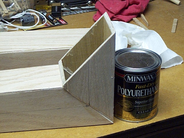
Prop the vertical (bottom bow) section with a heavy object
to prevent it from sliding out of alignment; the glue makes a good lubricant
when wet. Allow the glue to set.
In the same manner, lay the small 'up tube' section down and place the
'top bow' section onto it. Check alignment, glue and block as before (not
shown in photo). This sub-assembly can dry at the same time as the larger
assembly above.
|
|
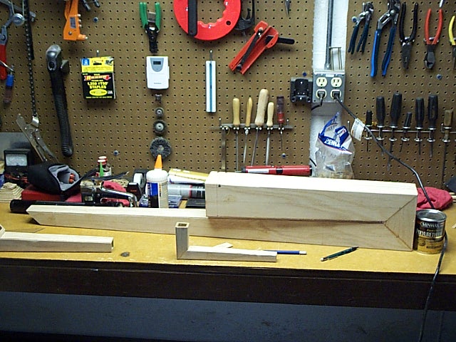
When the glue joints have completely cured, add the 'bell tube' section
to the 'down tube/bottom bow' assembly as shown. DO NOT GLUE YET!
The bell tube should be parallel to the down tube when the joint between
the bell tube and bottom bow sections is aligned. However, it will not
stay aligned without some added support; dowel sections will be used as
support spacers.
|
|
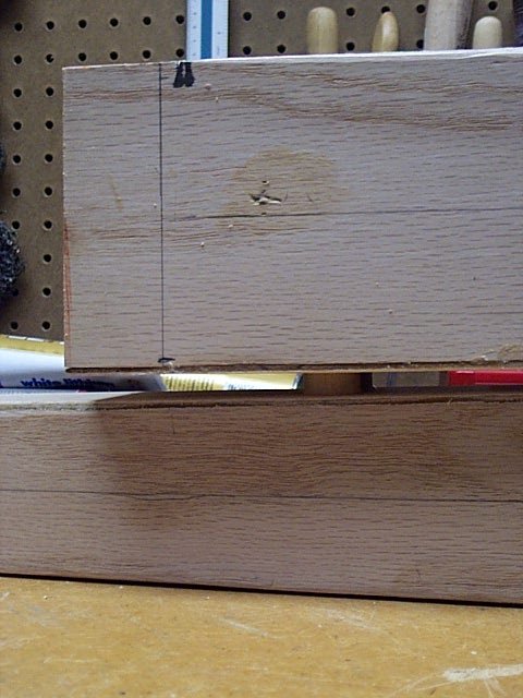
This photo shows a thin 3/4" diameter dowel section placed
as a spacer between the bell tube and down tube sections. Use four such
spacers, two near the bell end and two near the bottom bow. Due to slight
errors in cutting and alignment, it will probably be necessary to make
each spacer with slightly different lengths.
Note in the photo that a line has been drawn near the bell; this is
measured at about the 91" overall length point of the tube. During tuning,
it may be necessary to cut some of the bell end away, but it should never
be shorter than 91" unless something else is very wrong! Using this line
as a guide, make sure to place the spacers well clear of the area that
might be cut off later.
|
|
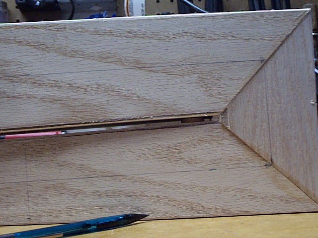
This photo shows the spacers near the bottom bow (visible in the shadows
between the tube sections). Also note how the center lines match up all
the way around the bottom bow 'bend'.
Once the spacers have been cut and test fit, apply wood glue to one
side of each spacer, and place them on the down tube; twist them slightly
while pushing down, to make for a better glue joint. Next, apply glue to
the tops of the spacers AND to the joint edges where the bell tube and
bottom bow meet. Place the bell tube in place, re-check alignment, and
make sure that the glue on the tops of the spacers has squeezed out somewhat
(a sign that the spacers fit correctly).
Wipe excess glue from the tube joint, and use cotton swabs to remove
excess glue at the spacers.
Block the bell tube to prevent shifting, and allow the glue to set.
|
|
Once the above assembly is dry, turn it over and add the 'up tube/top
bow' assembly. Here only two spacers are needed, since the tubing is not
so wide.
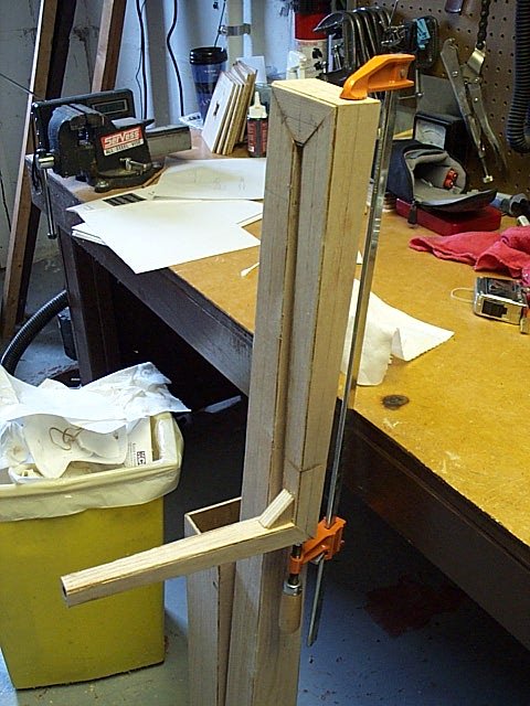
When all glue has completely set in the above assembly, add the final
'bocal' section. Prop the instrument up against a table, and fit the bocal
section to the up tube section. A pipe clamp, or other long reach clamp,
will work well for holding this joint together. If a clamp is not available,
wire, tape, etc; may be used with care.
Add a small piece of wood to the joint to reinforce it, as shown in
the photo.
This completes assembly of the Squarpent. Insert the mouthpiece and
perform the same bugle call tests as before. If any leaks are detected,
rub glue into the bend joints and allow to dry. Once the test is performed
successfully, proceed with drilling the finger holes.
All photos made using a Kodak DC240 digital
camera.
Go to next chapter
|
|