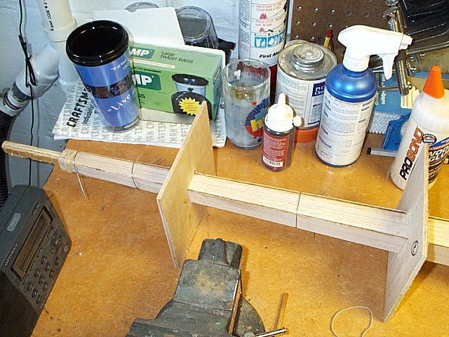
The next few photos show the trapezoids and outer jigs during the gluing
process. During gluing of the prototype, the piece of scrap plywood shown
in the small end of tube was replaced with the 1/2' dowel.
Note how the steel wire has been wrapped around the tube, twisted, and
then tightened by more twisting with a pliers.
|
|
Experience has shown that one or two wires are required between
each of the outer jigs.
It is better if the wires have been cut and are readily available before
the glue is applied.
|
|
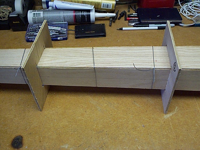
This photo shows how the end jigs, inner and outer, are located
somewhat short of the ends of the tube. This provides a margin of safety,
in case the jig dimensions are slightly off.
|
|
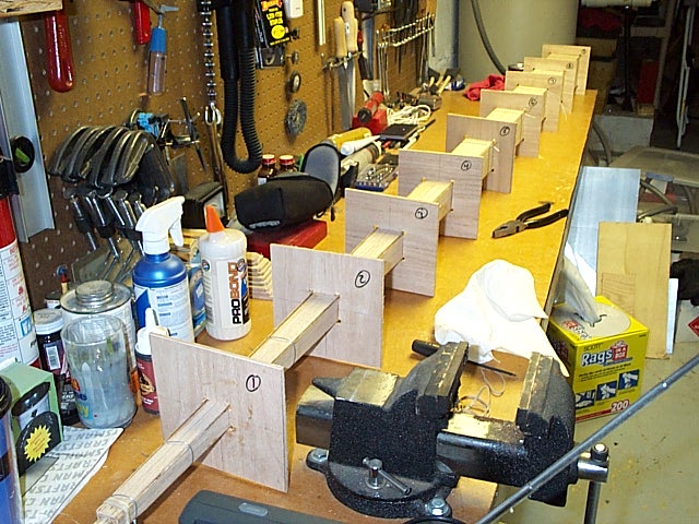
This photo shows the entire glue-up of the prototype. It is
apparent how the outer jigs are holding the assembly straight and true.
|
|
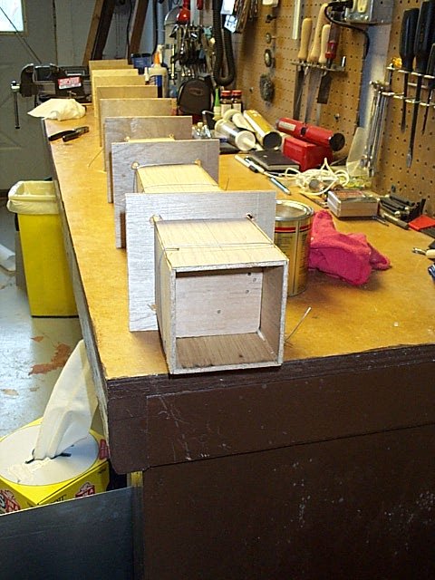
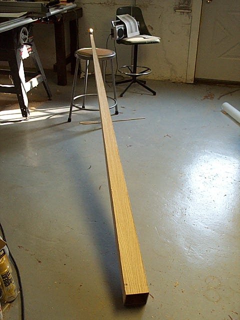
This photo shows the tube after the glue has set and the jigs
have been removed. A mouthpiece has been inserted into the square opening
and sealed with electrical tape; masking tape would have also worked.
At this point the basic integrity of the tube and its glue joints must
be tested. Bugle calls may be sounded easily (everyone knows 'Taps' and
'Reveille', but don't allow your choice to be a harbinger of your success
with the Squarpent project!), and the sound should be clear and distinct.
If the sound is suspect, smear more wood glue into the seams and work
into the rabbet joints, wiping off the excess. This should cure any leaks.
|
|
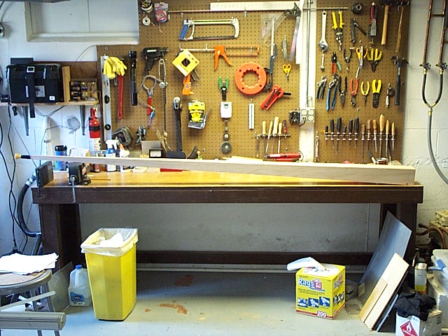
This photo shows a side view of the tube after testing.
It is now ready to get the mouthpiece receiver.
All photos made using a Kodak DC240 digital
camera.
Go to next chapter
|
|